ECE 275: Review
Announcments
- Midterm is on Oct 6th, 9 AM in class.
- 50 minutes.
- Notes on two-sides of a single 8.5x11 / A4 sheet are allowed.
- No calculator needed. Bring ruler for K-maps.
-
Review material
- Chapter 2 of textbook.
- Section 8.4 (Quine McCluskey method) of the textbook.
- Section 8.1 (Multi-level synthesis) of the textbook.
- Section 9.6 (Hazards) of the textbook.
- Link to Slides from Alfredo Benso for Functional decomposition.
- Link to handout from Steven Nowick for Quine McCluskey method.
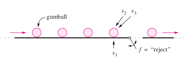
The figure depicts a part of a factory that makes bubble gumballs. The gumballs travel on a conveyor that has three associated sensors \( s_1 \) , \( s_2 \) , and \( s_3 \). The sensor \( s_1 \) is connected to a scale that weighs each gumball, and if a gumball is not heavy enough to be acceptable then the sensor sets \( s_1 = 1 \). Sensors \( s_2 \) and \( s_3 \) examine the diameter of each gumball. If a gumball is too small to be acceptable, then \( s_2 = 1 \), and if it is too large, then \( s_3 = 1 \). If a gumball is of an acceptable weight and size, then the sensors give \( s_1 = s_2 = s_3 = 0 \). The conveyor pushes the gumballs over a “trap door” that it used to reject the ones that are not properly formed. A gumball should be rejected if it is too large, or both too small and too light. The trap door is opened by setting the logic function \( f \) to the value 1.
Brown and Vranesic 2013, Example 2.7
- Find the minimial cost two-level circuit using K-maps (try both SOP/POS forms).
- Verify your answer using Quine McCluskey method (try only one of the forms).
- Try finding a lower cost implementation using functional decomposition with maximum fan-in of 2. Does functional decomposition lower the cost?
- Is the circuit hazard free? If not, design a Hazard free circuit.
Practice problem
\[ f(x_1, \dots, x_4) = \sum m(0, 2, 4, 5, 7, 8, 9, 15) \]Brown and Vranesic 2013, Problem 8.18
- Find the minimial cost two-level circuit using K-maps.
- Verify your answer using Quine McCluskey method.
- Try finding a lower cost implementation using functional decomposition with maximum fan-in of 2. Does functional decomposition lower the cost?
- Is the circuit hazard free? If not, design a Hazard free circuit.
Design a 3-bit 1's complement circuit
that complements a 3-bit signed magnitude representation \( x_2 x_1 x_0 \)Half adder
Design a Multi-output circuit that adds two 1-bit binary numbers \(x_0\) and \(y_0\) and outputs a sum and carry bit. \[ s_0 = (x_0 + y_0) \% 2 \] \[ c_0 = ( x_0 + y_0 ) // 2 \] where \( // \) stands for Quotient and \( \% \) for remainder.Full adder
Design a Multi-output circuit that adds three 1-bit binary numbers \(x_1\), \(y_1\) and \(c_0\) outputs a sum and carry bit. \[ s_1 = ( x_1 \boxplus y_1 \boxplus c_0) \% 2 \] \[ c_1 = ( x_1 \boxplus y_1 \boxplus c_0 ) // 2 \] where \( // \) stands for Quotient and \( \% \) for remainder.Decomposed Full adder
Design a Full adder in terms of two Half AddersRipple carry adder
Design a 4-bit adder using 4 Full addersGray code
Thanks, Questions, Feedback?
https://vikasdhiman.info/ECE275-Sequential-Logic/